
超级管理员 Fans & Motors
FFU Group Control: Modbus, 0–10V & BMS Basics
How FFU group control works—Modbus/RS485, 0–10V, zone balancing, filter-loading trim, and when networked EC arrays beat manual dials.
What is FFU group control?
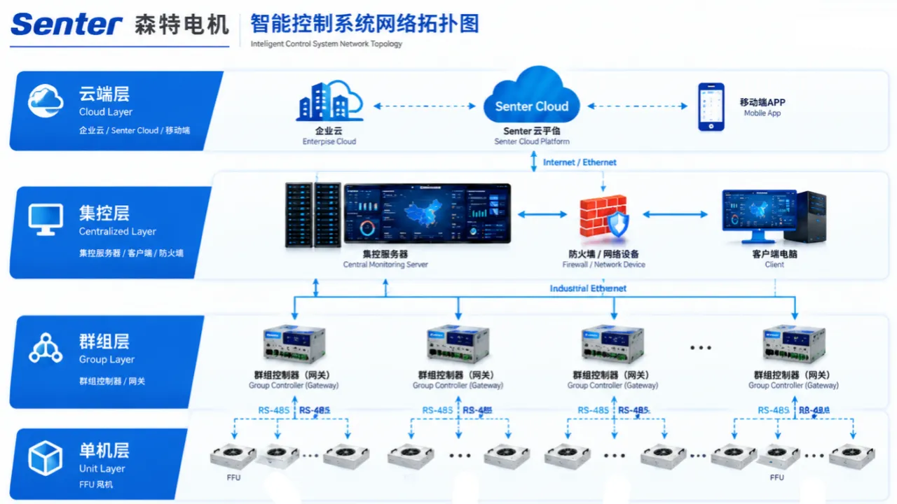
FFU group control is a networked (or multi-channel centralized) system that monitors and adjusts many fan filter units from one interface—commonly via RS485/Modbus or equivalent—so cleanroom airflow can be balanced by zone, trimmed as filters load, and set back when process allows, instead of relying on per-unit manual dials.
On small rooms with a handful of units, local speed pots can work. On semiconductor bays, pharma campuses, and large electronics halls—often dozens to thousands of FFUs—manual commissioning does not scale. Group control gives remote speed/status visibility and lowers maintenance burden.
Control interface belongs in the duty-point pack equal to airflow and final pressure drop—not as a last-week wiring surprise.
Why group control matters for ISO performance and OpEx
Group control protects ISO outcomes by keeping zone airflow adjustable through filter life, while cutting energy and noise by avoiding permanent “all units at max” operation.
Cleanroom classes remain defined by ISO 14644-1 particle limits. Your controls do not replace filtration physics; they keep supply airflow aligned with the design basis as HEPA/ULPA packs load (EN 1822 grades) and as rooms change duty.
| Without group control | With group control |
|---|---|
| Technicians walk ceilings with screwdrivers | Speed/status visible from a workstation |
| Night operation = day operation | Scheduled setback where process allows |
| Filter loading discovered at failure | Speed pegging / alarms trend early |
| Uneven zones hard to diagnose | Per-unit or per-zone trim |
| Energy locked at commissioning max | Trim to the minimum that still validates |
A typical estimate for EC FFUs is about 40–50% energy savings versus conventional AC and 2–3 year payback when 50+ units run 16+ hours/day, depending on duty-point watts and local tariff. Group control is how those savings stay real after month six—not only on the sales slide.
Coverage planning still applies: typical starting points are about 60–100% ceiling coverage for ISO 5 and about 25–40% for ISO 7, verified with ACH and process particle generation. Denser carpets amplify the value of networked trim.
Control architectures: 0–10V, RS485/Modbus, and hybrid
Most FFU projects land on analog speed (0–10 V / PWM), digital bus (RS485/Modbus), or a hybrid where a gateway translates BMS commands to groups of units.
| Architecture | How it works | Best fit | Watch-outs |
|---|---|---|---|
| Local pot / taps | Manual per unit | Under about 10 units, low change rate | No fleet visibility |
| 0–10 V / PWM | Analog speed command | Zones with shared setpoint | Wiring runs; limited diagnostics |
| RS485 / Modbus RTU | Addressed nodes on a bus | Mid-to-large arrays | Topology, termination, addressing |
| Gateway → BMS | Modbus/BACnet etc. at headend | Campus integration | Map points carefully |
| Hybrid | Bus inside room, analog at edge | Retrofits | Document both layers |
“Modbus” in FFU inquiries usually means Modbus RTU on RS485 unless Ethernet/TCP is explicitly stated. Always specify:
- Physical layer (RS485 two-wire, baud rate, parity)
- Addressing scheme and max nodes per segment
- Register map ownership (who publishes the point list)
- Fail behavior (last speed / safe speed on communications loss)
EC/DC motors make group control actually useful
Fine, stepless speed control on EC/DC platforms is what turns a network cable into airflow governance. Coarse AC taps networked poorly still behave like expensive switches.
EC/DC platforms allow stepless 0–100% control with fine increments and are usually quieter at comparable airflow because they can run slower—acoustics improve when you can run only as fast as validation requires.
Specify measured dB(A) at a stated distance and duty point. Group setback and balanced trim are how occupied rooms stay near that target instead of emergency max.
Pair controls with static-pressure reality: as filters load, speed rises to hold airflow inside the fan envelope. Controllers cannot invent static pressure beyond the curve.
Recommended point list (buyer-minded, not brand-locked)
Require a minimum point list so “Modbus-ready” means operable, not merely connector-ready.
| Point type | Examples | Why |
|---|---|---|
| Command | Speed setpoint (%), start/stop | Basic governance |
| Feedback | Speed feedback, run status | Closed-loop confidence |
| Alarms | Fault, communications loss, oversized speed | Maintenance triggers |
| Identity | Address, firmware/version | Fleet hygiene |
| Optional | Power estimate, pressure drop if sensed, HOA mode | Advanced campuses |
Fail-safe policy (write it down)
On communications loss, should FFUs: hold last speed, go to a defined safe %, or stop? The wrong default can either over-air a process or collapse ISO recovery.
Commissioning workflow for networked FFU arrays
Commission in layers—electrical → communications → airflow balance → documentation—and only then enable schedules.
- Verify power and rotation per unit.
- Address and terminate the bus; check segment length/node count.
- Poll each address; fix duplicates before balancing.
- Set initial speeds for clean-filter duty point.
- Validate particles / recovery against ISO basis.
- Back down speeds to the minimum that still passes.
- Record setpoints, maps, and as-built drawings.
- Enable setback schedules where process owners approve.
- Trend speed growth as a filter-loading proxy.
This sequence prevents the classic failure: perfect Modbus screenshots with every unit pegged at 100% forever.
When you need group control (decision thresholds)
Specify group control when unit count, runtime, multi-room complexity, or EH&S noise targets make manual dials irrational.
| Signal | Lean local control | Lean group control |
|---|---|---|
| Unit count | Under about 10–20 | 50+ or fast growth |
| Runtime | Single shift | 16–24 h multi-shift |
| Rooms | One small suite | Multi-suite campus |
| Filters | Rare changes | Tight ISO 5 carpet |
| Noise | Unoccupied | Occupied aisles / labs |
| OEM buyer | Fixed speed SKU | Private-label + BMS hookup |
Mapping to Senter Motor products
Ask for group-control-ready configurations on the module that already fits your grid—especially large rectangular halls.
| Project need | Senter shortlist cue |
|---|---|
| Group control + about 1500 m³/h class rectangular module | 1175×875 (DC 400, group-control module in standard configs) |
| High airflow about 1200 grid | 1175×1175 (DC 400, ≥2000 m³/h class)—specify network options in the inquiry |
| Narrower metric bays | 1175×575 (DC 310)—define 0–10 V / bus early |
| 600×600 modular | 615×615—confirm control interface with internal-rotor platform |
OEM/ODM private-label projects should freeze connector pinouts, address labeling, and English/Chinese HMI strings before mass production.
Inquiry block for controls (paste into emails)
Quantity / zoning drawing: ___
Per-unit interface: 0–10V / PWM / RS485 Modbus RTU / other ___
Baud / parity / addressing scheme: ___
Gateway / BMS protocol at headend (if any): ___
Minimum point list: setpoint, feedback, fault, address ___
Fail behavior on communications loss: hold / safe % / stop ___
EC/DC platform required: yes/no
Noise target at duty: ___ dB(A) @ ___ m
Airflow at initial and final filter pressure drop: ___
Conclusion
Use FFU group control—typically Modbus/RS485, sometimes 0–10 V, often behind a BMS gateway—whenever array size and runtime make manual speed pots a risk to energy, acoustics, and ISO stability.
Pair networked EC/DC platforms with honest duty points (final filter pressure drop included), write fail-safes and point lists into the inquiry, and commission by balancing then backing speed down. For hardware, review group-control-ready options such as Senter 1175×875 and related modules on senter-motor.com, then send zoning and protocol requirements for an integration-minded quote.
References
- ISO 14644-1:2015 — Classification of air cleanliness by particle concentration
- EN 1822 — High efficiency air filters (EPA, HEPA and ULPA)
Surround
FFU Static Pressure & Filter Loading Explained
Why FFU airflow falls as HEPA loads—initial vs final pressure drop, fan curves, EC constant-flow control, and inquiry fields that keep ISO performance stable.
FFU Housings: Galvanized vs Aluminized Zinc
Compare galvanized and aluminized-zinc FFU housings—0.8 mm vs 1.0 mm gauge, corrosion, stiffness, cleanroom fit, and what to put in the inquiry.