
超级管理员 Fans & Motors
FFU Static Pressure & Filter Loading Explained
Why FFU airflow falls as HEPA loads—initial vs final pressure drop, fan curves, EC constant-flow control, and inquiry fields that keep ISO performance stable.
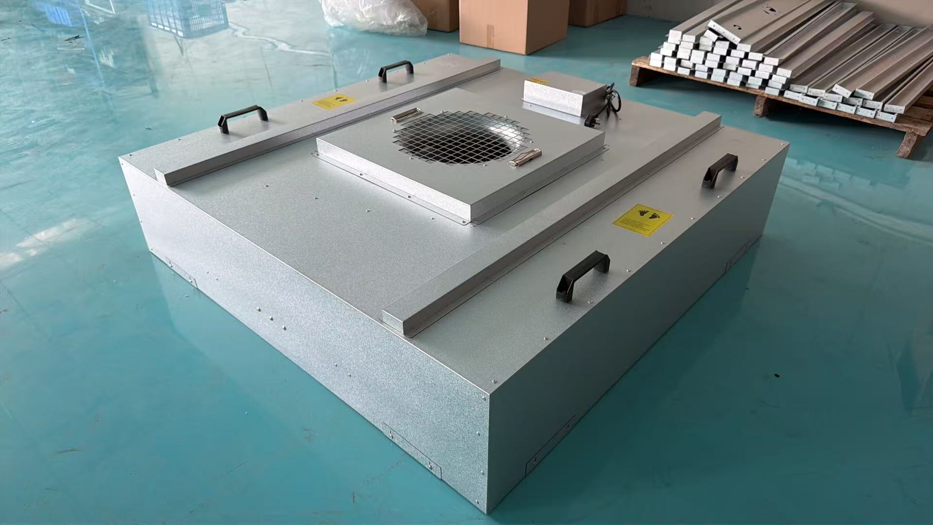
Why does FFU airflow fall months after startup?
Airflow falls because filter pressure drop rises as the media loads. If the fan cannot produce the required static pressure at an acceptable speed—or controls never raise speed—face velocity and ISO performance drift even though the FFU “still runs.”
Day-one commissioning on a clean HEPA pack is not end-of-life performance. Treat final filter pressure drop as a first-class selection input alongside airflow, cabinet height, noise, voltage, and control interface.
Static pressure in plain language (FFU context)
In an FFU, static pressure is the fan’s ability to push air through resistances—primarily the HEPA/ULPA pack, plus inlet/outlet effects, screens, and any secondary path losses—while delivering the target airflow.
Think of airflow (m³/h) as how much, and static pressure (Pa) as how hard the fan must push. Catalog “max airflow” with almost no resistance is not a cleanroom duty point. The duty point is the intersection of:
- The system resistance curve (filter + box + accessories), and
- The fan performance curve at a given speed.
As dust accumulates, the system curve steepens. The operating point slides unless speed/torque increases.
| Term | Meaning for buyers |
|---|---|
| Initial pressure drop | Pressure drop of clean installed filter at stated airflow |
| Final pressure drop | Change-out / design end-of-life pressure drop at stated airflow |
| Duty point | Target airflow at a defined pressure drop (usually include both initial and final) |
| Headroom | Extra fan capability beyond final pressure drop / max needed speed |
Filter classification language should stay consistent with EN 1822 (EPA/HEPA/ULPA at MPPS). Tighter grades generally mean higher pressure drop for a given face velocity.
EN 1822 classifies high-efficiency filters by performance at the most penetrating particle size (MPPS).
— EN 1822, High efficiency air filters (EPA, HEPA and ULPA)
Filter loading timeline: what actually changes
Loading increases media resistance, forcing a choice between lower airflow (if speed is fixed) or higher speed/power/noise (if controls compensate) until final pressure drop triggers replacement.
- Clean filter (initial pressure drop)
- Particles captured over months/years → rising pressure drop
- If fan/control cannot compensate → lower face velocity, slower recovery, ISO risk
- Or compensation within envelope → higher RPM, more kWh and dB(A)
- Replace at final pressure drop or integrity failure
Calendar rules of thumb (typically 1–3+ years depending on load) help spare planning. Differential pressure and integrity tests decide the real change-out.
Particle acceptance still references ISO 14644-1 class limits at the work plane. Static pressure engineering exists to keep supply airflow trustworthy against those limits.
ISO 14644-1 defines cleanroom air cleanliness classes by maximum allowable airborne particle concentrations.
— ISO 14644-1:2015
Constant airflow vs fixed speed: why EC/DC changes the story
EC/DC platforms with fine speed control (and optional constant-flow strategies) can raise RPM as pressure drop rises to hold airflow—within the motor’s torque, temperature, and noise envelope. Fixed-speed or coarse AC setups often cannot without manual retuning.
EC motors offer higher efficiency, especially at part load. A typical estimate is roughly 40–50% energy savings versus conventional AC at comparable duty and about 2–3 year payback when 50+ units run 16+ hours/day—depending on duty-point watts and local tariff. Stepless control also supports quieter operation when filters are clean (you do not need max speed on day one).
Critical limit: Constant-flow control cannot invent static pressure beyond the fan curve. If final pressure drop sits outside capability, the controller will drive toward max speed, noise climbs, and airflow still misses target.
Acoustic coupling is immediate: higher speed to fight pressure drop raises dB(A). Any quoted FFU noise figure assumes a workable operating speed, not an emergency max chase—specify measured dB(A) at a stated distance and at final-pressure-drop speed.
Group control as a fleet-level strategy
On large arrays, group control turns filter loading from a room-by-room guess into a monitored speed trend—enabling balanced trim, staged maintenance, and night setback without walking every dial.
Useful monitored signals
- Speed command / RPM proxy per unit
- Alarm when speed pegs near maximum
- Zone airflow or differential pressure where instrumented
- Filter change tickets triggered by pressure drop, not only by calendar
Senter’s 1175×875 configurations come with group-control readiness alongside DC external-rotor 400 platforms—a practical pairing for halls that will age through filter cycles.
The upgrade trap: H13 → H14/ULPA without re-curving
Changing filter grade mid-project is a new static-pressure specification. Keep the same housing only if the fan still hits airflow at the new final pressure drop.
| Change | What you hope | What often happens |
|---|---|---|
| H13 → H14 | “Cleaner air” | Higher pressure drop, higher speed, more noise |
| HEPA → ULPA | “Safer process” | Missed airflow if fan was marginal |
| Thicker pack in same box | “Easy retrofit” | Inlet conditions / height conflicts |
H13 (≥99.95% at MPPS per EN 1822 classification) is a common choice for mid-range electronics/food use, but it is a starting point only—always close with pressure drop versus curve.
Coverage/ACH quantity math (ISO 5 about 60–100% coverage, ISO 7 about 25–40%) still assumes each installed unit actually delivers its share of airflow through life—not only on the punch-list day.
How to put static pressure into the inquiry (non-negotiable fields)
Demand both ends of the filter life and the airflow at each end—plus noise and control—in one package.
Target airflow: ___ m³/h
Filter grade (EN 1822): H13 / H14 / ULPA ___
Initial pressure drop: ___ Pa @ target airflow
Final pressure drop: ___ Pa @ target airflow
Secondary resistances (grille/screen/prefilter): ___ Pa
Cabinet free height: ___ mm
Noise limit: ___ dB(A) @ ___ m at final-pressure-drop speed
Control mode: manual / 0–10 V / Modbus / constant-flow ___
Quantity + zoning: ___
| If supplier replies with… | Buyer action |
|---|---|
| Only “max m³/h” | Reject as incomplete |
| Airflow at 0 Pa | Ask for final-pressure-drop point |
| Noise without distance/speed | Incomplete acoustics |
| “EC is enough” without curve | Request curve + sample test |
Mapping static-pressure thinking to Senter platforms
Pick the module/fan family for grid and airflow class first, then prove final-pressure-drop capability on that platform.
| Module | Platform cue | Static-pressure conversation |
|---|---|---|
| 1175×575 | DC 310 external rotor | Shallow stack—confirm pack pressure drop early |
| 1175×1175 | DC 400, ≥2000 m³/h class | Higher airflow candidate; still verify final pressure drop |
| 1175×875 | DC 400 + group control | Best fit for fleet loading management |
| 615×615 | Internal rotor + 400 Al impeller | 600-grid duty points; 1.0 mm housing class |
OEM/ODM private-label projects should freeze filter frame standards before cosmetic design—gasket/gel and pack depth change pressure drop and integrity testing.
Troubleshooting low airflow through a pressure-drop lens
| Observation | Likely pressure-drop-related cause | Next measurement |
|---|---|---|
| Gradual airflow loss | Normal loading | Filter pressure drop vs baseline |
| Sudden loss after upgrade | Grade/pack change | New final pressure drop vs curve |
| Max speed, still low flow | Beyond fan envelope | Re-select fan/module |
| One zone worse | Uneven loading / control | Per-unit speed + local pressure drop |
| High noise + OK counts | Compensating successfully… for now | Plan change-out before hard stop |
Conclusion
Design FFUs for airflow at final filter pressure drop, monitor loading through pressure drop and speed trends, and use EC/DC + group control to compensate inside the fan envelope—never confuse a clean-filter startup test with lifecycle performance.
Keep EN 1822 and ISO 14644-1 in the written basis, reject free-air catalog maxima, and put initial/final pressure drop, noise, voltage, and control interface on every inquiry. For hardware shortlisting, compare Senter modules on senter-motor.com and send target airflow plus final pressure drop for a duty-point confirmation.
References
- EN 1822 — High efficiency air filters (EPA, HEPA and ULPA)
- ISO 14644-1:2015 — Classification of air cleanliness by particle concentration
Surround
FFU Noise Control: dB Specs That Actually Matter
How to specify cleanroom FFU noise—dB distance, duty-point speed, EC vs AC, filter loading, and inquiry language that prevents “quiet on paper, loud on site.”
FFU Group Control: Modbus, 0–10V & BMS Basics
How FFU group control works—Modbus/RS485, 0–10V, zone balancing, filter-loading trim, and when networked EC arrays beat manual dials.