
超级管理员 Knowledge
AC vs EC Motors in FFUs: Energy Savings & Payback
Compare AC vs EC/DC motors in cleanroom FFUs—efficiency, speed control, noise, group control, and when EC payback typically lands in the 2–3 year range for large fleets.
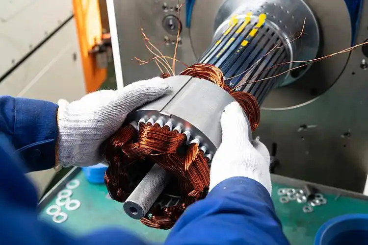
AC vs EC for FFUs — which should you choose?
For continuously operating cleanroom FFU fleets, EC/DC motors are usually the better lifecycle choice. They deliver higher part-load efficiency, stepless speed control, and cleaner integration with group control. Energy savings are typically about 40–50% versus conventional AC at comparable duty, depending on duty-point watts. AC motors remain viable for small rooms, short duty cycles, or hard CapEx caps.
This is not a slogan contest between “old AC” and “new EC.” It is a duty-point decision: airflow, final filter pressure drop, runtime hours, unit count, noise target, and whether you need networked speed trim. Buyers who pick a motor label without those inputs often get either wasted kilowatts or starved airflow after HEPA loading.
What “AC” and “EC/DC” mean inside an FFU
In FFU catalogs, “AC” usually means a conventional alternating-current fan motor (often with limited speed options). “EC” means an electronically commutated permanent-magnet motor—frequently implemented as a DC external-rotor platform with integrated electronics for precise speed control.
| Label you see | What it usually implies in FFU projects |
|---|---|
| AC FFU motor | Simpler drive, lower unit CapEx, coarser speed steps or tap settings |
| EC motor | Electronic commutation, high efficiency, stepless or fine speed control |
| DC external rotor (e.g. 310 / 400) | Compact FFU-friendly fan-motor assembly; often paired with EC-style control in modern cleanroom specs |
External-rotor geometries are popular in shallow FFU housings because the motor-impeller package fits limited ceiling depth while targeting high airflow at acceptable noise. Geometry still must clear filter pack height and wiring volume.
Side-by-side comparison
Compare AC vs EC on energy, controllability, acoustics, CapEx, and fleet operations—not on a single brochure watt number.
| Dimension | AC FFU (typical) | EC/DC FFU (typical) | Buyer takeaway |
|---|---|---|---|
| Efficiency | Lower at reduced speed / part load | Higher, especially at part load | EC wins on continuous part-load |
| Energy vs AC baseline | Baseline | Typically ~40–50% savings | Model your kWh; do not copy a headline blindly |
| Speed control | Limited taps / stepped | Stepless or fine-step speed control | Needed for balancing and setback |
| Group control / BMS | Possible but less elegant | Natural fit for 0–10 V / Modbus-style networks | Critical above about 50 units |
| Noise | Often higher at same airflow | Usually quieter at the same airflow because it can run slower | Specify measured dB(A) at a stated distance and duty point |
| Unit CapEx | Usually lower | Usually a higher unit price | Judge via payback |
| Best fit | Small rooms, low hours, tight CapEx | Multi-shift arrays, ISO-critical bays, OEM campuses | Match to runtime |
Why part-load efficiency dominates cleanroom OpEx
Most FFUs do not spend their life at a single “catalog max” point. They run for years at balanced speeds while filters slowly load. Part-load efficiency and controllable torque/airflow matter more than peak nameplate bravado.
Cleanroom arrays are closer to always-on infrastructure than to occasional HVAC fans. When filters are clean, many zones can run below maximum speed and still meet ISO particle limits. When filters load, speed must rise to hold airflow. EC platforms are built for that moving target. Fixed or coarse AC setups often get commissioned “all dials up,” locking in avoidable energy waste.
Particle performance itself remains anchored to ISO 14644-1 class limits. The motor’s job is to keep supply airflow trustworthy while the facility stays inside those limits.
ISO 14644-1 defines cleanroom classes by maximum allowable airborne particle concentrations—the reason FFU airflow must stay stable through filter life, not only on day-one startup.
— ISO 14644-1:2015
When EC payback shows up (and when it does not)
EC usually pays back fastest on large, long-runtime fleets. It pays back slowest on tiny rooms with short shifts and very cheap electricity.
A rough planning estimate:
- More than about 50 FFUs
- Running 16+ hours per day
- EC energy savings typically support a ~2–3 year payback versus AC
Treat that as a planning estimate, not a guarantee. Your real payback needs:
- Local industrial electricity tariff
- Measured or estimated watts per FFU at duty speed (not free-air fantasy)
- Filter change interval and final pressure drop
- Whether group-control setback is actually enabled overnight
Simple sketch (illustrative only):
If one AC FFU averages 180 W at commissioned speed and an EC equivalent averages 100 W for 16 h/day, 300 days/year:
ΔE ≈ 0.080 kW × 16 × 300 = 384 kWh/year per unit.
At $0.12/kWh ≈ $46/year per unit → $4,600/year on 100 units—before maintenance savings from networked monitoring.
Group control: the hidden multiplier of EC value
EC’s fine speed control becomes strategically valuable when FFUs are networked. That enables zone balancing, night setback, and remote fault visibility that manual AC dials cannot match at fleet scale.
Group control also cuts maintenance cost through remote speed and status monitoring. For OEM campuses and multi-room pharma or electronics sites, that operational layer often matters as much as the motor efficiency curve.
Senter product cue: large-format modules such as 1175×875 are offered with group-control readiness alongside DC external-rotor 400 platforms. 1175×575 (DC 310) and 1175×1175 (DC 400, ≥2000 m³/h class) map to projects that prioritize EC/DC-style controllable clean power.
Constant airflow vs “set and forget”
As HEPA/ULPA resistance rises, holding cleanroom airflow usually requires more fan speed and torque. EC constant-flow or monitored trim strategies are designed for that. Uncontrolled fixed settings are not.
Filter language should stay consistent with EN 1822 (EPA/HEPA/ULPA at MPPS). Upgrading from H13 to H14/ULPA without re-checking final pressure drop against the fan curve is a classic way to turn an “energy-saving EC project” into a low-flow complaint.
EN 1822 classifies high-efficiency filters by performance at the most penetrating particle size (MPPS)—and higher grades typically mean higher pressure drop that the FFU fan must overcome.
— EN 1822
Decision guide: pick AC or EC in five checks
Run five checks—runtime, fleet size, control need, acoustic limit, and CapEx horizon—then freeze the motor family.
| Check | Lean AC if… | Lean EC/DC if… |
|---|---|---|
| 1. Runtime | Under 8–12 h/day, seasonal | 16–24 h/day, multi-shift |
| 2. Fleet size | Under about 10–20 units | 50+ units (or growing to that) |
| 3. Controls | Local dial OK forever | BMS / Modbus / zone setback required |
| 4. Noise | Unoccupied / tolerant | Occupied aisles, optics, labs |
| 5. CapEx horizon | Must minimize day-one cost | Can invest for 2–3 year OpEx payback |
If checks 1–4 point to EC but check 5 blocks it, consider a hybrid rollout: EC on critical high-coverage bays first, AC on low-hour support rooms. Still standardize wiring and control documents to avoid spare-part chaos.
Inquiry checklist for motor-correct FFU quotes
Copy and paste into supplier emails:
- Module size (1175×575 / 1175×1175 / 1175×875 / 615×615 or opening drawing)
- Target airflow at initial and final filter pressure drop
- Filter grade (HEPA H13/H14 or ULPA) and face area if known
- Supply voltage / phases
- Control signal (0–10 V, PWM, RS485/Modbus, other)
- Noise target and measurement distance
- Quantity, zoning, and expected daily runtime
- Certificate mapping to SKU (CE, RoHS, ISO 9001; 3C if applicable)
Factories that build both core motors/fans and complete FFUs—Senter’s positioning—can shorten the interface loop when the duty point moves during design.
How this maps to Senter Motor platforms
Senter’s published complete FFU line leans on controllable DC external-rotor and internal-rotor platforms (DC 310, DC 400, and internal-rotor 400 aluminum impeller on 615×615). OEM and project buyers can specify clean-power hardware without separating “motor vendor” and “box vendor” on day one.
| Module | Motor/fan cue | EC/AC conversation starter |
|---|---|---|
| 1175×575 | DC 310 external rotor | Controllable DC platform for mid-bay modules |
| 1175×1175 | DC external rotor 400, ≥2000 m³/h class | High-airflow continuous-duty candidate |
| 1175×875 | DC external rotor 400 + group control | Fleet energy and networked balancing |
| 615×615 | Internal rotor + 400 Al impeller | Compact 600-grid duty-point selection |
Always validate on the curve at final filter pressure drop before calling any platform “the efficient choice.”
Conclusion
Pick EC/DC when FFUs run long hours at fleet scale and you need speed trim, group monitoring, and lower lifecycle energy. Pick AC when the room is small, hours are short, and CapEx is the binding constraint. Never pick either without a duty point.
Use typical planning estimates as anchors—roughly 40–50% energy savings and 2–3 year payback on 50+ / 16+ h fleets—then replace them with your tariff, measured watts, and measured dB(A) at the duty point. For hardware shortlisting, compare Senter modules on senter-motor.com and send the inquiry checklist above for an engineered AC-versus-EC recommendation.
References
- ISO 14644-1:2015 — Classification of air cleanliness by particle concentration
- EN 1822 — High efficiency air filters (EPA, HEPA and ULPA)
Surround
FFU Sizes Explained: 1175×575 vs 1175×1175 vs 615×615
Compare cleanroom FFU sizes—1175×575, 1175×1175, 1175×875, and 615×615—by ceiling grid, airflow, DC 310/400 fans, and ISO coverage needs.
How to Select an FFU for ISO Class Cleanrooms
Step-by-step FFU selection for ISO cleanrooms—coverage ratios, ACH, module size, EC vs AC, HEPA/ULPA, and an inquiry checklist that gets accurate quotes.