
超级管理员 Selection
How to Select an FFU for ISO Class Cleanrooms
Step-by-step FFU selection for ISO cleanrooms—coverage ratios, ACH, module size, EC vs AC, HEPA/ULPA, and an inquiry checklist that gets accurate quotes.
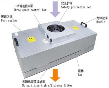
How do you select an FFU for an ISO cleanroom?
Select an FFU by locking the ISO (and process) target first, then calculating airflow or ceiling coverage, matching the real ceiling module size, choosing motor and control strategy, and verifying that the fan can hold airflow at the filter’s final pressure drop—not by picking the largest catalog photo.
Cleanroom buyers who reverse that order—“we like 1175×1175, send a quote”—create change orders later: wrong grid fit, starved H14 upgrades, or energy bills from “all dials to max” commissioning. This guide gives a repeatable five-step workflow built around the full duty point.
ISO 14644-1 defines air cleanliness classes by maximum allowable concentrations of airborne particles—your FFU count, filter grade, and airflow stability exist to defend those limits at the work plane.
— ISO 14644-1:2015, Cleanrooms and associated controlled environments — Part 1
Step 1 — Define the cleanliness target (ISO class + process risk)
Write down the ISO class you must validate, plus whether the process generates extra particles, solvents, or heat that raise the real airflow demand above “empty room” math.
Use ISO 14644-1 language in the specification so purchasing, HVAC, and validation share one vocabulary. Then add process notes:
| Question | Why it changes FFU selection |
|---|---|
| ISO 5 vs ISO 7 vs ISO 8? | Coverage density and often filter grade |
| Open product / wafer / aseptic critical? | Higher integrity and documentation bar |
| Manned vs mostly automated? | Noise and setback strategy |
| New build vs retrofit? | Grid and height constraints dominate |
Do not stop at “pharma cleanroom” or “electronics room.” Those labels are markets; ISO class + process risk are specifications.
Step 2 — Calculate how many FFUs you need (coverage or ACH)
Estimate quantity with either ceiling coverage ratio (class-based planning) or air changes per hour (ACH), then divide total required airflow by the candidate unit’s duty-point airflow.
Method A — Coverage ratio (fast planning)
Typical planning ranges, as a starting point to verify with ACH and process particle generation:
| ISO planning band | Typical ceiling coverage |
|---|---|
| ISO 5 | about 60–100% |
| ISO 7 | about 25–40% |
First-pass count:
FFU count ≈ (Ceiling area × coverage %) ÷ FFU face area
Then reconcile with ACH and particle generation.
Method B — ACH (airflow basis)
Total airflow (m³/h) = Room volume (m³) × ACH
FFU count ≈ Total airflow ÷ Unit airflow (m³/h at duty point)
Add margin for leakage, balancing, and filter loading. Day-one clean-filter airflow is not end-of-life airflow.
Mini example (illustrative)
- Room: 12 m × 8 m × 3 m → volume 288 m³
- Target: 60 ACH → total airflow 17,280 m³/h
- Candidate: 1175×1175 at 2,000 m³/h duty assumption
- Raw count: 17,280 ÷ 2,000 ≈ 8.6 → 9–11 units after margin and layout constraints
Always re-check against coverage geometry: nine units may be correct on paper but wrong if the grid cannot place them uniformly over the critical zone.
Step 3 — Lock mechanical fit (module size + height)
Match the FFU envelope to the real ceiling opening and available height before you fall in love with an airflow number.
| If your grid conversation is… | First shortlist |
|---|---|
| About 1200×1200 international | 1175×1175 |
| About 600×600 modular | 615×615 |
| Narrower 575 / 1200×600-class | 1175×575 |
| Large rectangular modules + zoning | 1175×875 |
Remember: 1175 exists to fit nominal 1200 grids with gasket and edge clearance; 615 pairs with 600 systems. Still verify exact openings with the ceiling vendor.
Cabinet height constrains fan and filter stack options. Neither a fan curve nor a housing drawing is enough on its own—send both, with the final filter pressure drop.
Senter map: DC 310 on 1175×575; DC external-rotor 400 on 1175×1175 (≥2000 m³/h class) and 1175×875 (about 1500 m³/h class, group control); internal-rotor 400 aluminum impeller on 615×615 (1.0 mm housing class).
Step 4 — Select motor and controls (AC vs EC/DC + group control)
Choose EC/DC when units run long hours at fleet scale and you need fine speed trim or BMS/group control. Choose AC when rooms are small, hours are short, and CapEx is the binding constraint.
Typical EC/DC advantages to plan with:
- Higher efficiency, especially at part load
- Roughly 40–50% energy savings versus conventional AC (typical estimate; depends on duty-point watts)
- About 2–3 years payback when 50+ FFUs run 16+ hours/day (rough planning estimate; depends on local tariff)
- Stepless speed control, and usually quieter operation at comparable airflow because the fan can run slower
For occupied electronics or lab aisles, acoustics matter too. Specify measured dB(A) at a stated distance and duty point.
Control note: If you need night setback or multi-room balancing, specify protocol early (0–10 V, RS485/Modbus, and similar). Retrofitting networking after install is more expensive than designing it in.
Step 5 — Match filter grade to fan static pressure (HEPA vs ULPA)
Pick HEPA H13/H14 for most ISO 5–8 FFU applications. Step up to ULPA only when the process needs higher efficiency on smaller particles—and only after confirming initial and final filter pressure drop against the fan curve.
Keep specification language consistent with EN 1822 (EPA/HEPA/ULPA at MPPS). A higher filter grade that the fan cannot drive produces low airflow, higher noise at emergency speeds, and failed validation—not “cleaner air.”
EN 1822 classifies high-efficiency filters by filtration performance at the most penetrating particle size (MPPS).
— EN 1822, High efficiency air filters (EPA, HEPA and ULPA)
| Typical direction | Filter conversation | FFU implication |
|---|---|---|
| Broad electronics / food / mid ISO | HEPA H13 (≥99.95% per EN 1822) | Confirm pressure drop versus fan |
| Tighter ISO 5 / critical bays | H14 or ULPA | Need airflow headroom |
| Any upgrade mid-project | “Same box, tighter filter” | Re-validate duty point |
H13 is a common choice for mid-range electronics/food use. Treat that as a starting heuristic, then engineer the pressure drop.
One-page selection workflow
- ISO class + process risk
- Coverage % and/or ACH → total airflow → unit count (+ margin)
- Ceiling grid + height → module family (1175×575 / 875 / 1175 / 615×615)
- Runtime + fleet size → AC vs EC/DC + group control protocol
- HEPA/ULPA grade → initial and final pressure drop → confirm fan duty point
- Certificates (CE/RoHS/ISO 9001; 3C if applicable) + OEM docs → inquiry
Common selection mistakes (and how to avoid them)
| Mistake | What goes wrong | Fix |
|---|---|---|
| Size before ISO target | Wrong density / wasted CapEx | Step 1 first |
| Using free-air max m³/h | Low flow after HEPA install | Specify duty-point pressure drop |
| Ignoring grid drawings | Units do not seal | Step 3 with ceiling vendor |
| AC on a 200-unit multi-shift fab | OpEx shock | Model EC payback |
| ULPA without fan headroom | Noise + failed counts | Step 5 re-curve |
| No control spec | Manual chaos at scale | Require protocol in the inquiry |
Inquiry template that gets accurate quotes
Send this block to suppliers (including OEM/ODM factories):
- Room L×W×H, ISO class, process notes
- Target coverage % or ACH
- Ceiling grid / exact opening + available height
- Preferred module family (or “recommend”)
- Airflow at initial and final filter pressure drop
- Filter grade (H13/H14/ULPA)
- Voltage; control protocol; noise target
- Quantity + zoning drawing
- Certificate and labeling requirements
- Annual volume / private-label rules (if OEM)
Factories that own both motor/fan platforms and complete FFU assembly—Senter’s model—can iterate duty points without a three-vendor blame loop.
How to shortlist Senter modules after the five steps
After ISO math and grid fit, shortlist Senter’s four published complete FFUs by module—then confirm duty-point curves and documentation packs.
| Project signal | Shortlist |
|---|---|
| 1200-class grid, high airflow bay | 1175×1175 (DC 400, ≥2000 m³/h class) |
| Rectangular hall + networked balancing | 1175×875 (DC 400 + group control, about 1500 m³/h class) |
| Narrower metric module / support zones | 1175×575 (DC 310) |
| 600×600 modular fit-out | 615×615 (internal rotor 400 Al impeller, 1.0 mm housing) |
Conclusion
ISO-class FFU selection is a sequence—class → quantity → size → motor/control → filter/duty point—not a single SKU decision.
Anchor planning with coverage bands (about 60–100% for ISO 5, about 25–40% for ISO 7), defend particle limits with ISO 14644-1 language, specify filters with EN 1822 vocabulary, and demand operating-point data at final filter pressure drop. When you are ready for hardware, use the inquiry template above and compare modules on senter-motor.com for an engineered shortlist.
References
- ISO 14644-1:2015 — Classification of air cleanliness by particle concentration
- EN 1822 — High efficiency air filters (EPA, HEPA and ULPA)
Surround
AC vs EC Motors in FFUs: Energy Savings & Payback
Compare AC vs EC/DC motors in cleanroom FFUs—efficiency, speed control, noise, group control, and when EC payback typically lands in the 2–3 year range for large fleets.
External vs Internal Rotor Fans for Cleanroom FFUs
Compare external-rotor vs internal-rotor FFU fans—compact depth, airflow, noise, DC 310/400 platforms, and how to select by duty point rather than architecture labels.