
超级管理员 Fans & Motors
External vs Internal Rotor Fans for Cleanroom FFUs
Compare external-rotor vs internal-rotor FFU fans—compact depth, airflow, noise, DC 310/400 platforms, and how to select by duty point rather than architecture labels.
External rotor or internal rotor for FFUs?
Choose external-rotor or internal-rotor FFU fans by the duty point and housing limits—airflow, final filter pressure drop, housing height, noise, voltage, and control interface—not by which architecture sounds more “advanced.”
Both geometries move cleanroom air through HEPA/ULPA packs. External-rotor platforms dominate many modern shallow ceiling FFUs because the motor and impeller form a compact, high-airflow package. Internal-rotor designs remain the right answer when the module, impeller metallurgy, and legacy spare-parts strategy are built around that architecture—for example Senter’s 615×615 unit with an internal-rotor motor and 400 aluminum impeller.
What “external rotor” and “internal rotor” mean
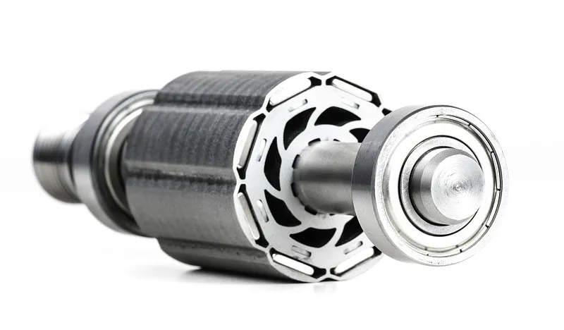
In an external-rotor fan, the rotor (and typically the impeller hub) spins around a stationary stator—putting rotating mass at a larger diameter inside a short axial package. In an internal-rotor fan, the rotor spins inside the stator in a more conventional motor layout, usually coupled to a separately mounted impeller.
| Architecture | Mechanical idea | Why FFU designers care |
|---|---|---|
| External rotor | Stator inside; rotor/impeller outside | Short stack height, integrated motor-impeller, strong fit for shallow FFU boxes |
| Internal rotor | Rotor inside stator; impeller attached | Familiar motor form factor; flexible impeller materials and geometries (for example, aluminum) |
For cleanroom ceilings, stack height is not a detail—it is often the constraint that kills an otherwise perfect airflow curve. Plenums are crowded with grids, lights, fire services, and filter packs. A fan that “wins” on a bench curve but does not fit the housing loses the project.
Why external-rotor fans are so common in ceiling FFUs
External-rotor fans are common in FFUs because they deliver high airflow in limited cabinet depth with a compact motor-impeller assembly suited to laminar ceiling modules.
Typical engineering motives:
- Shallow housings — metric FFUs must leave room for HEPA depth, inlets, and wiring.
- Integrated rotating assembly — fewer interfaces between motor shaft and impeller hub.
- EC/DC controllability — modern external-rotor platforms pair naturally with stepless speed control and group networks.
- Array economics — when you install dozens to thousands of units, compact repeatable assemblies simplify OEM tooling.
Senter’s published large and mid modules lean on this family:
| Module | External-rotor cue | Airflow conversation starter |
|---|---|---|
| 1175×575 | DC 310 external rotor | Stable laminar supply for narrower grids |
| 1175×1175 | DC external rotor 400 | ≥2000 m³/h class high airflow |
| 1175×875 | DC external rotor 400 | About 1500 m³/h class + group control |
These are still not “auto-select” SKUs. Final HEPA/ULPA pressure drop, noise, and voltage must land on the curve.
When internal-rotor + aluminum impeller is the better shortlist
Shortlist internal-rotor fans when your ceiling standard, spare-parts plan, or impeller performance target is built around that layout—especially on 600×600 modular grids using 615×615 FFUs.
Senter’s 615×615 cleanroom ceiling FFU uses an internal-rotor motor + 400 aluminum impeller, with a 1.0 mm housing class for mechanical strength and corrosion resistance. That combination targets uniform laminar supply on compact grids common in electronics, pharmaceutical modular fit-outs, and food clean upgrades.
Why aluminum impeller language appears in inquiries
- Stiffness-to-weight balance for centrifugal geometries
- Predictable balance quality for noise-sensitive occupied rooms
- Clear spare-part identity for maintenance teams
Internal rotor is not “legacy only.” It is a deliberate platform choice when the module ecosystem (grid, filter frame, service access) was designed around it.
Side-by-side comparison for buyers
Compare architectures on fit, service model, acoustics, and duty-point margin—not on marketing adjectives.
| Dimension | External rotor (typical FFU use) | Internal rotor (typical FFU use) |
|---|---|---|
| Cabinet depth fit | Often stronger in shallow boxes | Depends on motor + impeller stack |
| Integration | Motor-impeller highly integrated | More separable motor/impeller service stories |
| Common Senter map | DC 310 / DC 400 on 1175 families | 400 Al impeller on 615×615 |
| Control pairing | Frequent with EC/DC speed and group control | Also controllable; specify protocol explicitly |
| Best first question | “What is housing free height?” | “What grid and spare standard are we on?” |
| Failure mode to avoid | Ignoring final filter pressure drop | Assuming 600-grid projects must use 1175 modules |
Energy and acoustics still track motor drive technology (AC vs EC/DC) as much as rotor layout. EC holds higher efficiency, especially at part load, typically saves roughly 40–50% energy versus conventional AC, and as a rough planning estimate pays back in about 2–3 years when 50+ units run 16+ hours/day—depending on duty-point watts and local tariff. EC FFUs are also usually quieter at the same airflow because they can run slower; specify measured dB(A) at a stated distance and duty point.
Duty point first: the non-negotiable selection rule
Rotor type is a means; airflow at final filter pressure drop is the end.
Cleanroom particle limits come from ISO 14644-1. Filter grades should be specified with EN 1822 vocabulary (HEPA/ULPA at MPPS). Neither standard cares whether your rotor is inside or outside the stator—both care that classified air actually arrives at the work plane for the life of the filter.
Practical sequence:
- Fix ISO class / process risk (coverage or ACH).
- Lock ceiling module + housing height.
- Set airflow + initial/final filter pressure drop.
- Shortlist external vs internal platforms that fit the box.
- Confirm noise, voltage, and control protocol.
- Only then freeze DC 310 vs DC 400 vs internal-rotor 400 Al.
ISO 14644-1 classifies air cleanliness by airborne particle concentration; EN 1822 classifies high-efficiency filters by MPPS performance—together they define why the fan must hold duty through filter life.
— ISO 14644-1:2015; EN 1822
Decision path (two minutes)
- Already standardized on 600×600 / 615×615? Start with internal-rotor + 400 Al impeller.
- Cabinet height tight on a 1175-class module? Start with external-rotor DC 310 or DC 400.
- Need ≥2000 m³/h class on about 1200 grid? Shortlist external-rotor DC 400 / 1175×1175.
- Need group control on large rectangular modules? Shortlist external-rotor DC 400 / 1175×875.
- Otherwise compare both families on the curve at final pressure drop.
OEM/ODM notes: interface risk sits between motor and box
If you private-label FFUs, prefer a supplier that can own both the fan-motor platform and the housing—so impeller clearance, inlet conditions, and wiring conventions are one accountable stack.
Classic multi-vendor failure: motor supplier signs off a curve, box supplier signs off a drawing, filter pack arrives heavier than assumed, and the installed array misses face velocity. External vs internal rotor arguments then become politics. A source-factory model (motor core → fan → complete FFU) shortens that loop.
Send on day one
- Opening / module size and free height
- Target airflow at initial and final pressure drop
- Filter grade and face area
- Noise target
- Voltage + control signal
- Quantity / zoning
- Branding and certificate mapping (CE, RoHS, ISO 9001; 3C if applicable)
How Senter Motor maps rotor platforms to modules
| If you need… | Rotor platform | Module shortlist |
|---|---|---|
| Narrower metric bay, compact DC platform | External rotor DC 310 | 1175×575 |
| Large 1200-class high airflow | External rotor DC 400 | 1175×1175 |
| Rectangular bay + networked balancing | External rotor DC 400 + group control | 1175×875 |
| 600×600 modular clean fit-out | Internal rotor + 400 Al impeller | 615×615 |
Conclusion
External-rotor fans excel when shallow 1175-class FFUs need compact, controllable high airflow (DC 310 / DC 400). Internal-rotor + aluminum impeller platforms excel when 600-grid modules and service standards are built around that architecture (615×615). Neither wins without a verified duty point at final filter pressure drop.
Use ISO coverage and ACH to set count, EN 1822 language to set filtration, and cabinet height to shortlist rotor geometry. Then compare live modules on senter-motor.com and send your duty point, final filter pressure drop, and housing free height for an engineered recommendation.
References
- ISO 14644-1:2015 — Classification of air cleanliness by particle concentration
- EN 1822 — High efficiency air filters (EPA, HEPA and ULPA)
Surround
How to Select an FFU for ISO Class Cleanrooms
Step-by-step FFU selection for ISO cleanrooms—coverage ratios, ACH, module size, EC vs AC, HEPA/ULPA, and an inquiry checklist that gets accurate quotes.
HEPA vs ULPA for FFUs: Which Filter Grade to Spec
Compare HEPA H13/H14 vs ULPA in cleanroom FFUs—EN 1822, MPPS efficiency, pressure drop, ISO class pairing, and how to avoid low-airflow failures after a filter upgrade.