
超级管理员 Selection
How to Calculate Cleanroom ACH and FFU Quantity
Calculate how many FFUs you need using ACH or ISO coverage ratios—worked examples for 1175×1175 and 615×615 modules, plus margin for filter loading.
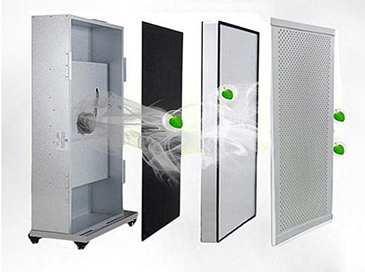
How many FFUs do you need?
Estimate FFU quantity from either air changes per hour (ACH) or ISO-class ceiling coverage, then divide total required airflow by the selected unit’s duty-point airflow (m³/h at the relevant filter pressure drop)—and add margin for balancing, leakage, and filter loading.
“Order twelve 1175s” is not a calculation. Cleanroom particle performance is judged against ISO 14644-1 limits at the work plane; FFU count is one of the engineered controls that keep those limits honest.
ISO 14644-1 defines cleanroom classes by maximum allowable concentrations of airborne particles—your ACH/coverage math exists to support that classification in operation, not only on a spreadsheet.
— ISO 14644-1:2015
Method A — ACH (air changes per hour)
ACH converts room volume into a total airflow target, which you then split across FFU modules.
Core formulas
Room volume (m³) = L × W × H
Total airflow (m³/h) = Room volume (m³) × ACH
FFU count (raw) = Total airflow (m³/h) ÷ Unit airflow (m³/h)
FFU count (design) = Raw count × (1 + margin)
Margin guidance (engineering judgment, not a code):
Many project teams start with roughly 10–25% margin for layout constraints, leakage, and filter loading—then reconcile with ceiling grid geometry. Dense ISO 5 carpets may be geometry-limited before they are ACH-limited.
What ACH number should you use?
ACH targets are project-specific (process, occupancy, recovery time, owner standards). This article does not invent a fake universal ACH table. Instead:
- Take ACH from the cleanroom design basis / owner spec.
- If only ISO class is known, use coverage Method B as a parallel check.
- Never back-calculate ACH from a supplier’s marketing brochure alone.
Worked example A1 — Mid-size room, 1175×1175 modules
Given
- Room: 10 m × 8 m × 3.0 m
- Volume: 10 × 8 × 3 = 240 m³
- Design ACH: 60 / h (example only)
- Candidate unit airflow at duty point: 2,000 m³/h (1175×1175 “≥2000 m³/h class” conversation starter)
- Margin: 15%
Calc
- Total airflow = 240 × 60 = 14,400 m³/h
- Raw count = 14,400 / 2,000 = 7.2 → 8 before margin
- With 15% margin = 7.2 × 1.15 ≈ 8.3 → 9 FFUs (round up)
Reality check: Can nine 1175×1175 modules place uniformly on an about-1200-class grid over the critical zone? If the ceiling only allows six openings over tools and three elsewhere, redesign layout or mix module sizes—do not force the spreadsheet.
Worked example A2 — Same airflow need, 615×615 modules
Given
- Same total airflow: 14,400 m³/h
- Assume a compact-grid unit duty airflow of 900 m³/h (illustrative—replace with your cut-sheet duty point)
- Margin: 15%
Calc
- Raw count = 14,400 / 900 = 16
- With margin = 16 × 1.15 = 18.4 → 19 FFUs
Takeaway: Smaller face modules need more units for the same ACH. That is normal on 600×600 grids—plan structure, wiring, and group control early.
Method B — Ceiling coverage ratio
Coverage ratio estimates how much of the ceiling should be active FFU face area for a target ISO planning band—then converts area into module count.
Core formulas
Required FFU face area = Ceiling area × Coverage %
FFU count ≈ Required FFU face area ÷ One module face area
Typical planning bands (starting points)
These are typical planning ranges, not code values—verify them against ACH and process particle generation.
| ISO planning band | Typical ceiling coverage |
|---|---|
| ISO 5 | about 60–100% |
| ISO 7 | about 25–40% |
Worked example B1 — ISO 7 hall
Given
- Ceiling: 20 m × 12 m = 240 m²
- Coverage target: 30% (inside the 25–40% ISO 7 band)
- Module: 1175×1175 → face ≈ 1.175 × 1.175 ≈ 1.38 m²
Calc
- Required face = 240 × 0.30 = 72 m²
- Count = 72 / 1.38 ≈ 52.2 → 53 FFUs (before aisle/lighting deductions)
Then convert to airflow: 53 × (duty m³/h per unit) and compare with ACH Method A. If the two methods disagree by a wide margin, your ACH assumption, coverage assumption, or unit airflow is inconsistent—fix inputs before buying.
Worked example B2 — ISO 5 critical bay
Given
- Ceiling over critical bay: 8 m × 6 m = 48 m²
- Coverage target: 80% (inside 60–100%)
- Module face ≈ 1.38 m² (1175×1175)
Calc
- Required face = 48 × 0.80 = 38.4 m²
- Count = 38.4 / 1.38 ≈ 27.8 → 28 FFUs
Dense carpets make group control, electrical diversity, and filter-change logistics as important as the raw number.
Always convert count back to a fan duty point
Unit count is wrong if the “m³/h per FFU” was a free-air catalog maximum instead of airflow at final filter pressure drop.
HEPA/ULPA packs should be specified with EN 1822 language. Higher grades (H14/ULPA) generally raise pressure drop. If filters load and speed cannot recover airflow, your carefully calculated 28-unit ISO 5 bay becomes an under-ventilated bay with expensive wallpaper.
EN 1822 classifies HEPA/ULPA performance at MPPS; higher efficiency grades must still be paired with fans that can overcome initial and final pressure drop.
— EN 1822
EC/DC platforms help hold airflow as pressure drop rises and can cut energy versus conventional AC on long-runtime fleets (a typical estimate is about 40–50% savings and 2–3 year payback for 50+ units at 16+ h/day, depending on duty-point watts and local tariff)—but they do not erase bad quantity math.
Module cheat sheet for substituting into the formulas
Use these as shortlist inputs, then replace with approved curves:
| Senter module | Grid conversation | Airflow cue to plug in cautiously | Notes |
|---|---|---|---|
| 1175×575 | narrower / 1200×600-class | Mid-bay laminar (use cut-sheet duty m³/h) | DC 310 external rotor |
| 1175×1175 | About 1200×1200 | Start from ≥2000 m³/h class only if duty pressure drop allows | DC 400 external rotor |
| 1175×875 | large rectangular | Start from about 1500 m³/h class + group control | DC 400 |
| 615×615 | 600×600 | Use verified compact-grid duty m³/h | Internal rotor + 400 Al impeller |
Face area for coverage math (approximate):
- 1175×1175 ≈ 1.38 m²
- 1175×875 ≈ 1.03 m²
- 1175×575 ≈ 0.68 m²
- 615×615 ≈ 0.38 m²
Step-by-step workflow (for PE / PM)
- Get ISO class + owner ACH or coverage basis
- Compute Method A and/or Method B
- Pick module family from real ceiling grid
- Insert duty-point airflow (final filter pressure drop)
- Round up + apply margin
- Overlay openings, lights, sprinklers, walkable constraints
- Recheck total airflow and zone uniformity
- Freeze motor/control (EC/DC, group protocol)
- Issue inquiry with L×W×H, ISO, pressure drop, quantity, zoning drawing
Common counting mistakes
| Mistake | Symptom | Fix |
|---|---|---|
| Using free-air max m³/h | Low flow after HEPA install | Duty-point pressure drop only |
| ACH without layout check | Units do not fit openings | Grid overlay in Step 6 |
| Coverage without airflow check | Pretty carpet, wrong ACH | Run Method A in parallel |
| Ignoring filter loading | Counts drift in 6–18 months | Final pressure drop + speed headroom |
| One size for every room | Overspend or underperform | Mix 1175 / 615 families by zone |
| No electrical/control plan for 50+ units | Commissioning chaos | Group control early |
Mini inquiry for a free takeoff
Send to engineering/sales:
- Room L×W×H (or CAD)
- ISO class + ACH or coverage target
- Ceiling grid / opening schedule
- Preferred module(s) or “recommend”
- Filter grade + initial/final pressure drop
- Voltage, noise, control protocol
- Zoning drawing (critical vs support)
Senter can map results onto 1175×575 / 1175×1175 / 1175×875 / 615×615 complete FFUs and OEM variants without inventing customer case studies.
Conclusion
Calculate FFU quantity with ACH and/or ISO coverage, divide by duty-point unit airflow, round up with margin, then force the number to survive real ceiling geometry and final filter pressure drop.
Use typical coverage bands (about 60–100% for ISO 5, about 25–40% for ISO 7) as starting points, keep ISO 14644-1 and EN 1822 in the written basis, and demand operating-point data (airflow at final filter pressure drop, noise, voltage, control). When you want a checked takeoff, share room data via senter-motor.com and shortlist modules against the math—not against catalog photography.
References
- ISO 14644-1:2015 — Classification of air cleanliness by particle concentration
- EN 1822 — High efficiency air filters (EPA, HEPA and ULPA)