
超级管理员 Knowledge
What is an FFU? Fan Filter Unit Guide for Cleanrooms
An FFU (Fan Filter Unit) is a ceiling module with a fan and HEPA/ULPA filter that supplies filtered laminar air to cleanrooms. Learn how FFUs work, how they differ from AHUs, and what to compare when you select one.
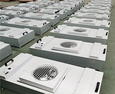
What is an FFU?
An FFU — Fan Filter Unit — is a self-contained cleanroom ceiling module that integrates a fan, motor, and high-efficiency filter (HEPA or ULPA). It draws air from a plenum or return path and supplies filtered laminar airflow into a controlled space.
If you are specifying equipment for semiconductor, pharmaceutical, electronics, food, or laboratory cleanrooms, the FFU is usually the modular “last meter” of air cleanliness. It sits in the ceiling grid, removes airborne particles, and pushes a uniform downward air curtain toward the work plane. Unlike a single large air handler that conditions an entire building, FFUs scale room by room and zone by zone—from a handful of units in a small ISO 8 suite to thousands of units in a high-coverage ISO 5 bay.
ISO 14644-1 defines cleanroom air cleanliness classes by maximum allowable concentrations of airborne particles at specified particle sizes. That classification envelope is what FFU arrays are engineered to support.
ISO 14644-1 defines cleanroom air cleanliness classes by maximum allowable concentrations of airborne particles at specified particle sizes.
— ISO 14644-1:2015, Cleanrooms and associated controlled environments — Part 1
Why FFUs matter in modern cleanrooms
Cleanrooms succeed or fail on particle control, pressure cascades, and validated airflow. Modular FFUs matter because they let designers:
- Match coverage to ISO class — denser packing for tighter classes, lighter packing for mid-range rooms.
- Service filters and fans locally — without shutting down an entire central plant.
- Tune zones independently — especially when EC/DC motors and group control are used.
- Grow capacity incrementally — add modules when a process bay expands.
Class drives density strongly. As a typical planning range, ISO 5 spaces may need about 60–100% ceiling coverage, while ISO 7 often plans around 25–40% coverage—a starting point to verify with ACH and process particle generation. Those percentages—not marketing slogans—determine whether you buy dozens or hundreds of FFUs.
How a Fan Filter Unit works
An FFU pulls air into the unit, forces it through a HEPA/ULPA filter, and discharges a controlled, roughly unidirectional airflow into the cleanroom.
A typical ceiling FFU airflow path:
- Intake — room return air or plenum air enters the housing.
- Fan pressurization — a centrifugal fan (often external-rotor DC/EC in modern units) builds static pressure.
- Filtration — air passes a sealed HEPA or ULPA pack sized to the module.
- Supply — filtered air exits as a downward laminar (or low-turbulence) stream.
- Room recirculation — air moves to low-wall or floor returns and repeats.
Two engineering details decide whether the unit works only on paper or still works after six months:
- Filter pressure drop rises over time. Dust loading increases resistance. If the fan cannot overcome final pressure drop, airflow collapses and ISO counts drift.
- Face velocity and uniformity matter. Cleanroom performance is judged at the work plane, not only at the filter face.
FFU vs AHU: what is the difference?
An FFU is a modular ceiling filtration and supply unit. An AHU (Air Handling Unit) is a central machine that heats, cools, dehumidifies, and moves bulk air for a building or suite.
| Dimension | FFU | AHU |
|---|---|---|
| Role | Final HEPA/ULPA supply at the ceiling | Central conditioning and primary air movement |
| Scalability | Add or remove modules per zone | Sized as large plant equipment |
| Filtration emphasis | Terminal high-efficiency filtration | Pre/intermediate filtration; may feed FFU plenums |
| Controls | Per-unit or group speed control | BMS for coils, fans, dampers, economizers |
| Typical failure mode | Filter load or local imbalance | Coil, damper, or central fan issues |
In many advanced cleanrooms the architecture is hybrid: AHUs condition and pressurize, while FFU arrays deliver the classified laminar blanket. Specifying one does not automatically replace the other.
Core FFU specifications buyers actually compare
1) Module size and ceiling grid
Common metric modules include 1175×575, 1175×875, 1175×1175, and 615×615, typically aligned to 600/1200-class cleanroom grids. Size is a mechanical fit decision first—then an airflow decision.
2) Airflow (m³/h or CFM)
Airflow must be stated at a defined static pressure. Catalog “max airflow” without filter final pressure drop is not a duty point. Large 1175×1175 DC platforms typically sit in the ≥2000 m³/h class; other modules may sit nearer ~1500 m³/h depending on fan and filter pack. Always confirm on the curve.
3) Filter grade (HEPA vs ULPA)
Most ISO 5–8 FFUs use HEPA H13/H14. ULPA is reserved for processes that need higher efficiency on smaller particles.
EN 1822 classifies EPA/HEPA/ULPA performance at MPPS (most penetrating particle size). A higher filter grade that the fan cannot drive is a failed specification.
EN 1822 defines EPA, HEPA, and ULPA filter classes based on filtration efficiency at the most penetrating particle size (MPPS).
— EN 1822, High efficiency air filters (EPA, HEPA and ULPA)
4) Motor technology (AC vs EC/DC)
For continuously operating FFU fleets, EC/DC motors usually win on energy, speed control, and group-control readiness.
EC motors hold higher efficiency, especially at part load, and typically save roughly 40–50% energy versus conventional AC at comparable duty. As a rough planning estimate, payback is about 2–3 years when 50+ units run 16+ hours per day—the actual figure depends on duty-point watts and local tariff. EC units are also usually quieter at the same airflow because they can run slower; specify measured dB(A) at a stated distance and duty point.
5) Housing, noise, and controls
Housings commonly use 0.8–1.0 mm aluminized zinc or galvanized steel for stiffness and corrosion resistance. Noise targets should be written into the inquiry. Group control (RS485/Modbus and similar) turns a sea of local dials into a balanced, monitorable array—especially valuable beyond about 50 units.
How many FFUs do you need? (quick method)
Estimate from air changes per hour (ACH) or from ISO-class ceiling coverage, then divide total required airflow by the selected unit’s rated airflow at duty point.
ACH method:
Total airflow (m³/h) = Room volume (m³) × ACH
Unit count ≈ Total airflow ÷ Unit airflow
Add margin for leakage, balancing, and filter loading.
Coverage method: apply class-based ceiling coverage (for example, denser for ISO 5, lighter for ISO 7), convert covered area into module count, then verify ACH and particle performance in validation.
Neither method replaces a project engineer’s calculation—but both prevent the common error of ordering “some 1175 units” without a particle or airflow basis.
FFU applications by industry
| Industry | What FFUs typically solve | Spec cues |
|---|---|---|
| Semiconductor / microelectronics | High coverage laminar supply | Dense packing, H14/ULPA in critical bays, high airflow headroom |
| Pharmaceutical / biotech | Classified suites and localized higher grades | Documented HEPA integrity, cleanable materials, validation support |
| Electronics / optics assembly | Stable mid-class particle control plus operator comfort | 600×600 or 1200×600 grids, noise-aware EC/DC |
| Food / hygienic packaging | Particle control over open product | Durable housings, serviceable filters, predictable OEM lead time |
Senter Motor maps these needs to four published modules—1175×575 (DC 310), 1175×1175 (DC 400, ≥2000 m³/h class), 1175×875 (DC 400, ~1500 m³/h class, group control), and 615×615 (internal rotor 400 aluminum impeller, 1.0 mm housing)—so buyers can shortlist by grid first.
OEM/ODM: when the factory stack matters
If you need private-label FFUs or a matched motor-to-housing interface, prefer a manufacturer that can own both the core fan/motor platform and the complete unit.
Vertical integration reduces the classic blame loop (“motor is fine / box is wrong / filter pressure drop was underestimated”). Day-one inquiries should include grid opening, airflow, initial and final filter pressure drop, voltage, noise, control protocol, quantity, and branding rules.
Five questions to ask before you buy
- What ISO class (and process particle risk) are we actually validating?
- What is the ceiling grid and available height?
- What airflow is required at final filter pressure drop?
- Do we need EC/DC speed control and group monitoring?
- Which certificates and documents ship with the exact SKU (CE, RoHS, ISO 9001, 3C where applicable)?
If a supplier cannot answer question 3 with a duty-point discussion, keep shopping.
Conclusion
An FFU is the modular cleanroom engine that turns plenum air into validated, filtered laminar supply. Select it by grid fit, duty-point airflow, filter grade, motor and control strategy, and lifecycle energy—not by catalog photos.
Use the comparison notes on senter-motor.com to shortlist a module, then send your operating point for an engineered recommendation. For continuously running arrays, evaluate EC/DC and group control early. For classified spaces, keep ISO 14644-1 particle limits and EN 1822 filter language in the specification so purchasing, engineering, and validation share one vocabulary.
References
- ISO 14644-1:2015 — Cleanrooms and associated controlled environments — Part 1
- EN 1822 — High efficiency air filters (EPA, HEPA and ULPA)
Surround
How to Calculate Cleanroom ACH and FFU Quantity
Calculate how many FFUs you need using ACH or ISO coverage ratios—worked examples for 1175×1175 and 615×615 modules, plus margin for filter loading.
FFU Sizes Explained: 1175×575 vs 1175×1175 vs 615×615
Compare cleanroom FFU sizes—1175×575, 1175×1175, 1175×875, and 615×615—by ceiling grid, airflow, DC 310/400 fans, and ISO coverage needs.